Hu-Lift
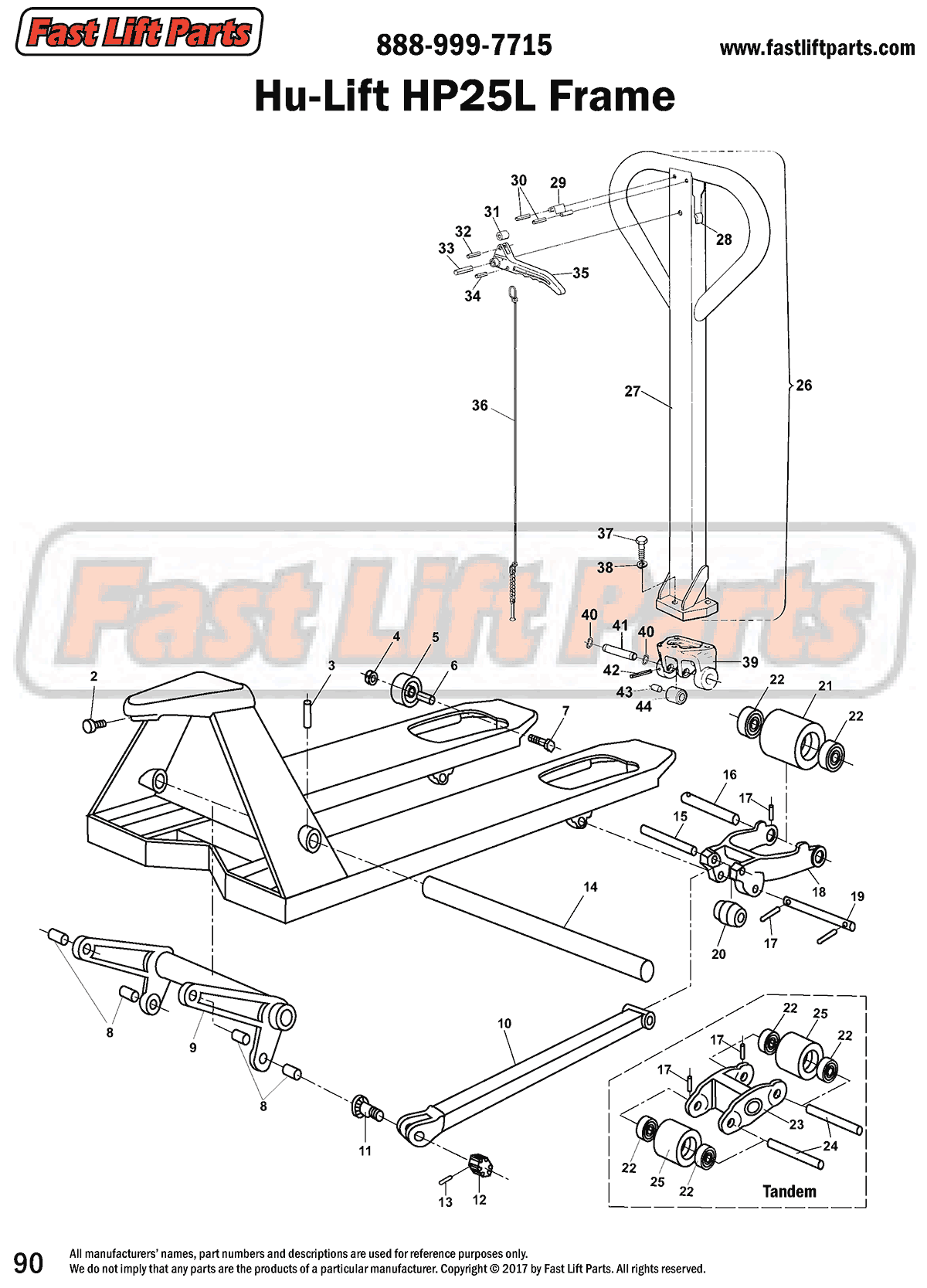
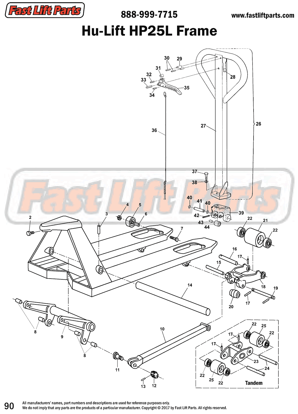
*Hu-Lift HP25L Frame
Identify your part using this line drawing of the frame.
Locate a part on the hydraulic unit.
- HL F103 Hex Socket Screw
- HL F104 Roll Pin
- HL F106 Nut
- HL F108 Entry Roller
- HL F109 Sleeve
- HL F111 Bolt
- HL F102 Bushing
- HL F101 Lifting Link Assembly
- HL F125 Push Rod
- HL F126 Eccentric Pin
- HL F123 Nut
- HL F124 Split Pin
- HL F105 Lifting Link Shaft
- HL F122 Push Rod Axle
- HL F121 Load Wheel Axle
- HL F112 Roll Pin
- HL F120 Load Roller Bracket
- HL F118 Axle
- HL F119 Roller
- Load Roller Assembly Options
- HL F115 Bearing
- HL F113 Load Roller Bracket
- HL F114 Load Roller Axle
- Load Roller Assembly Options
-
HL H101-A Handle Assembly
(includes Items 27-36) - See Handle Assembly
- HL H108 Rubber Cushion
- HL H103 Handle Spring
- HL H104 Roll Pin
- HL H111 Nylon Roller
- HL H105 Roll Pin
- HL H102 Roll Pin
- HL H112 Roll Pin
- HL H106 Control Lever
- HL H107 Rod & Chain. NLA, see HL H101-A.
- HL H109 Handle Bolt
- HL H110 Lock Washer
-
HL 103 Handle Bracket
HL 103-A Bracket Assembly - HL 108 Snap Ring
- HL 107 Shaft
- HL 106 Roll Pin
- HL 105 Bushing
- HL 104 Steel Roller


